Capacitors Introduction and Modelling
Exploring the basic component that can store voltage
What are capacitors?
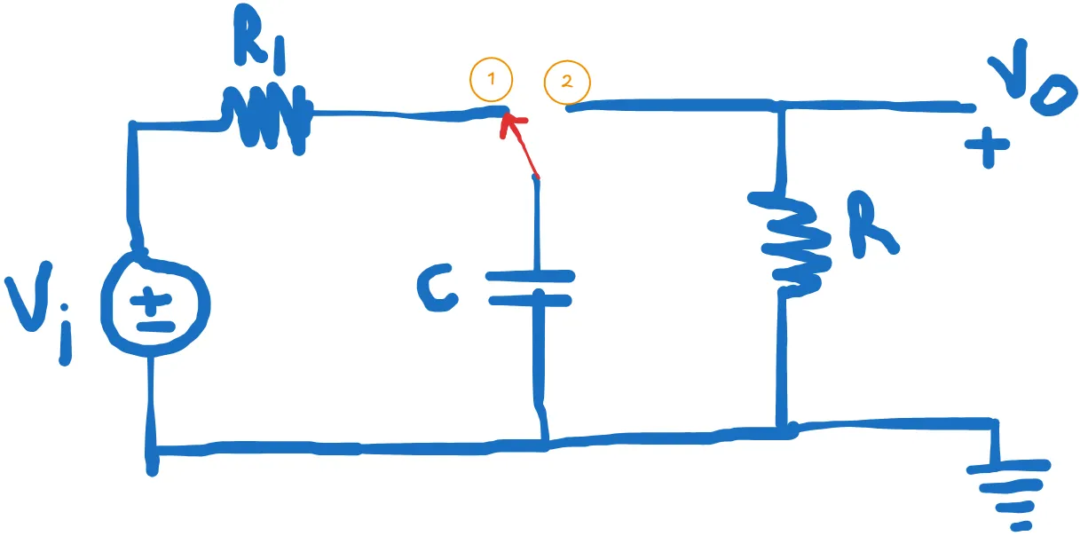
Figure 1: Base Circuit Image
- A capacitor is defined as a passive component which is used for storing electrical energy. A capacitor is made of two conductors that are separated by the dielectric material. These dielectric materials are in the form of plates which can accumulate charges.
- One plate is for a positive charge while the other is for a negative charge.
- Capacitance is the effect of the capacitor. Capacitance is defined as the ratio of electric charge Q to the voltage V and it is expressed as
Where,
- Q is the electric charge measured in coulombs
- C is the capacitance measured in farad
- V is the voltage across the plates measured in volts
Capacitors Modelling
Starting with the Capacitor modelling equation:
And now assuming that the circuit is operating for 0 to time t we get:
This formula states that the current I measured in amps, flowing in a capacitor is equal to the capacitance C measured in farads times the rate change of voltage measured in volts per second. Figure above shows the schematic symbols used for capacitors and the current direction convention (+ to – is positive).
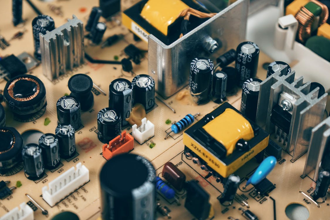
Notice that some capacitors are polarized, others are bipolar or monolithic. Typically, polarized capacitors have much larger values that monolithic or bipolar types.
Capacitor Charging and Discharging states
RC Discharging Analysis
The current going out of capacitor in diagram 2 above is :
is negative below as current flows from capacitor into the opposite side as in the second image above
Hence, this can be resolved as:
This is the differential function, this means that the slope of the function equals some constant times the function.
The equation
Taking the derivative of this function at time will result in:
Substituting we get following equation:
considering we get:
And the final equation that we get for discharging of capacitor after substituting above equation inside is:
where RC is the time constant.
The equations that we solved above depicts the following chart:
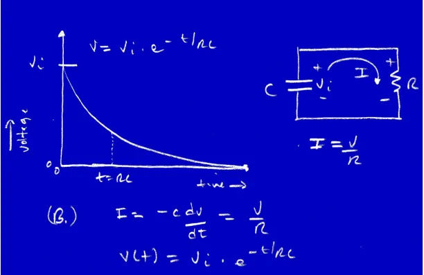 This is how the graph looks when capacitor is discharging.
RC Charging Analysis
Considering that the voltage is driving out of batter in diagram 1 above, we can assume that the capacitor is at 0 charge on it at the moment before closure, we can write a simple equation that describes the circuit.
The circuit is driven with a voltage source Vi, this creates a current thru resistor R that charges C, the current Ic must be the same through the resistor as well as the capacitor, so we can write:
Deriving, also from the formula we can write:
Here we do because as per the diagram, we consider source voltage - voltage across capacitor. So, our modeling equation becomes:
This is first order differential and based on the equations inside RC discharging at :
plugging V into the modeling equation along with the derivative of V with respect to we get:
Right at the moment of closure of the switch that is t=0-, (0- means an infinitesimal amount of time before 0, and similarly 0+ means an infinitesimal amount of time after 0) the capacitor had 0 charge on it, therefore, 0V. Hence, we can write this
Hence, substituting the value of A as in we get:
RC Charging results in table:
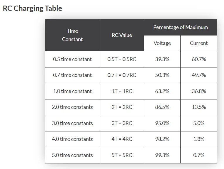 image from electronics-tutorials.ws
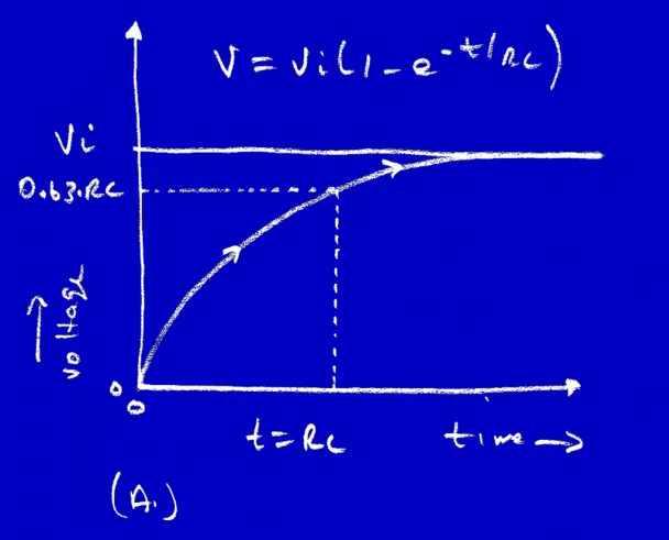
From the table above we can substitute the values inside the final equations and can prove that at 5RC times our capacitor will be almost 99% fully charged:
Assuming, we’re using 9v battery to energize the circuit shown in diagram 1 of capacitor charging circuit, then substituting 9v and 5rc times in the formula we get,
Below is the graph that we get for the equation we solved in